MS-002 · Design & Manufacturing
Air Engine & Blender Attachment
Overview
EML2322L opens by showing you a working compressed-air engine. From there the course runs on two tracks at once.
In the lab, you manufacture that air engine yourself, part by part across the semester on manual mills and lathes, then assemble it. That's the hands-on half, and it ends with an engine you made that actually runs.
On paper, you design an attachment for it. The brief was something that bolts onto the existing air engine and mixes the contents of a standard wide-mouth mason jar. It is a design exercise. The attachment is taken through full CAD and a manufacturing plan, but never cut. That work is Design Reports 1 through 3.
The engine with my blender attachment
The engine driving the Design Report 1 blender attachment, belt, jar and all.
Design Report 1, my attachment design
DR1 is individual, so everyone designs their own attachment. Mine is a two-speed, belt-driven blender.
Drive. A modified flywheel takes power from the engine. A steel retaining lip is welded around its upper outer diameter to stop the belt climbing off under load, and the flywheel sits flush with the aluminum base so the belt stays in plane through the whole run.
Tensioning. A movable tensioner assembly of an arm, a bearing, and a retaining nut rides in a slotted cutout in the base. Sliding it changes belt tension to suit the drive diameter in use, and a nut tightened from underneath locks it in place. The bearing rides on the outer face of the belt, so it keeps alignment and tension without adding friction.
Two speeds. The vertical output shaft runs on bearings top and bottom and carries two drive diameters, both turnable in one lathe setup. The larger lower diameter gives slower, higher-torque mixing, and the smaller upper one gives higher speed. Both have retaining lips. Changing speed means stopping the engine and moving the belt between them, which is a mechanical gear selector with no extra parts.
Output. An Oster drive pin threads directly into the top of the shaft and passes through the lid platform to drive a standard Oster blade assembly. A food-grade rubber gasket seals between the rotating blade and the lid components, and a lid adapter bonded to the lid with food-safe silicone threads onto a wide-mouth mason jar. The completed lid assembly twist-locks to the platform bayonet-style, so the jar comes on and off in one motion but stays constrained while running.
Design Reports 2 and 3, selection and refinement
DR2 puts you in a group to evaluate everyone's individual designs against each other and pick the strongest one objectively rather than by preference. My group had three members.
DR3 takes the selected design and finishes it with refined CAD, detail drawings, and a written manufacturing process outline covering how each part would be made and inspected.
Manufacturing the air engine
Running alongside all of that is the shop work. I machined four of the engine's parts from raw stock on the manual mill and lathe. The base, the flywheel, the piston, and the piston block. Each one had to hold the tolerances its bearing fits and sealing faces demanded, get inspected against its drawing, and then go into the assembly and actually run.
The engine as built
The four parts I machined, plus the manifold, bearings and fasteners between them.
The finished engine, running on shop air
Design reports
The three reports that carry the attachment from an individual design through group selection to a finished, manufacturable package, and the submitted paperwork alongside them.

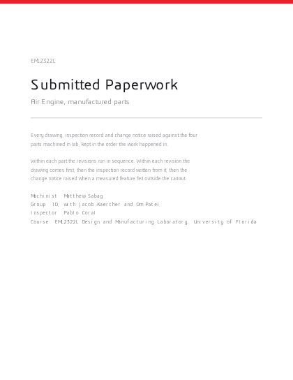
Submitted paperwork
Separate from the reports, and more interesting. Every part machined in lab carries a paper trail, and the trail is the point. A detail drawing defines the part. A manufacturing inspection record is written from that drawing and lists every dimension with its datum, nominal value, tolerance, and the tool used to check it. If a measured feature falls outside the callout, you raise an engineering change notice against it.
Plenty of features did fall outside the callout, and that is what the revisions are. The parts were not scrapped and re-cut. Each deviation was measured, checked against the assembly to see whether it actually mattered, and then either the drawing was corrected or the tolerance was widened to something the feature genuinely needed. Every change is written down with the reasoning behind it, then the drawing and the inspection record are reissued at the new revision.
Reading through them, the changes fall into four kinds.
- A part measured out of spec and the deviation turned out to be harmless. Base 2 came off the machine with a 0.412 in counterbore against a 0.30 in nominal. Checking the assembly in SolidWorks confirmed the bushing still seated and still cleared the flywheel, so the callout was reissued at 0.350 ±0.062 rather than the part being thrown away.
- A dimension was toleranced tighter than its job required. The flywheel height was held to ±0.005 and parts kept failing on it for no functional reason, so it went to ±0.020. Fourteen dimensions on the piston block went the same way. Over-tolerancing costs machining time and inspection time and buys nothing.
- The drawing was wrong or impossible to work from. A Ø0.625 hole does not correspond to a standard end mill, so it became Ø0.6875, which is 11/16 in. A Ø0.150 hole was undersized for the 10-24 UNC fastener going through it and became Ø0.157, the standard tap drill. Two holes on the piston block had no locating dimensions at all. One depth callout should always have read thru.
- A constraint outside the drawing changed. A team member left, so the build quantity dropped from 4 to 3 across every part. That is still a change to a released drawing, so it still gets an ECN.
One point worth clarifying. The measured column on the inspection records is empty. Those are the inspection plans, one reissued per revision, and the actual measured values live in the change notices where they were used to justify each revision.
All of it is merged into one file above, in the order the work happened. Every part, then every revision in sequence, then the drawing, the inspection record, and the change notice for that revision. There is a contents page at the front and bookmarks in the sidebar.
What I took away
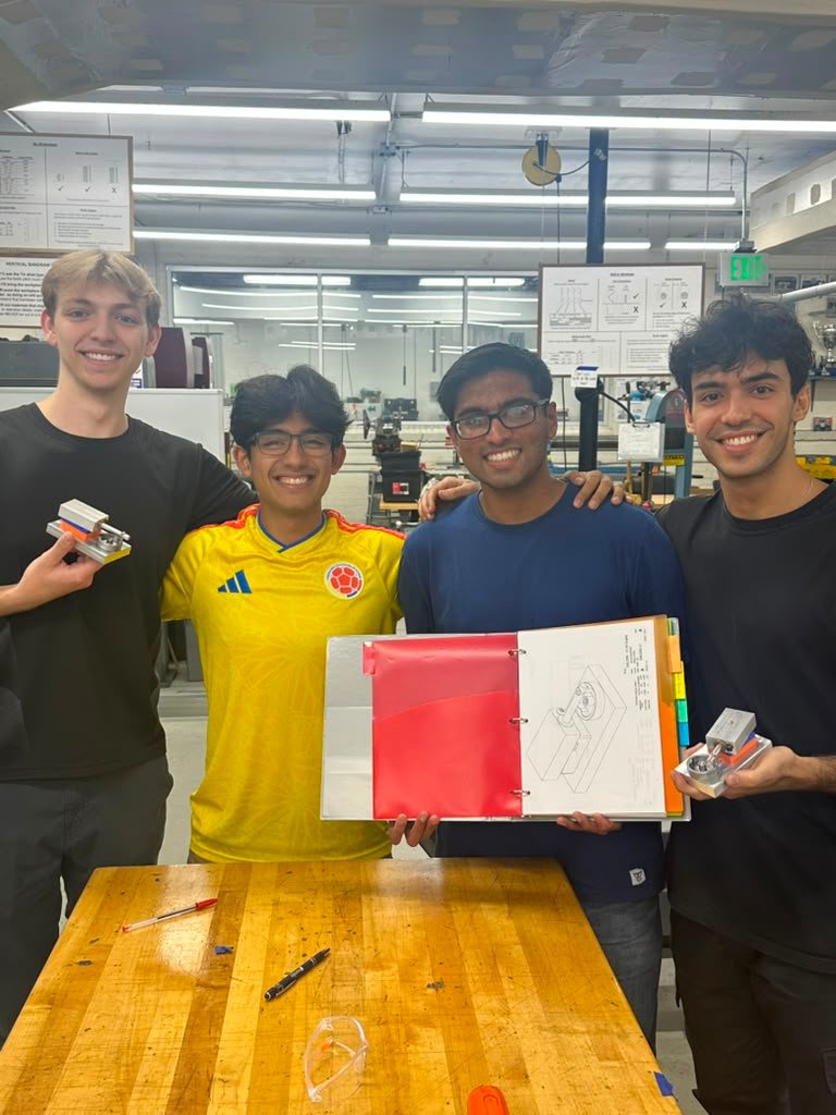 The shop crew, end of semester
The engines in that photo only run because every part in them was drawn first, cut to the drawing, measured against it, and then corrected wherever it missed. Nothing about that is glamorous and all of it is the job.
The revisions taught me more than the parts did. Being handed back a measurement that failed and having to decide whether the drawing was wrong or the part was is a different skill from making the cut, and it is the one I would want to be trusted with.